Electrical Schematic Drawing Symbols
Electrical Schematic Drawing Symbols - Web common symbols found in wiring schematics include those for power sources, switches, relays, resistors, capacitors, transformers, motors, and various electrical connections. What are the basic electrical symbols? Web there are a number of standards for schematic symbols and how to interconnect them. The resistor symbol represents each light bulb. Basics 13 valve limit switch legend : Web this tutorial should turn you into a fully literate schematic reader!
The symbols represent electrical and electronic components. Web an electronic symbol is a pictogram used to represent various electrical and electronic devices or functions, such as wires, batteries, resistors, and transistors, in a schematic diagram of an electrical or electronic circuit. Each symbol represents a specific electrical component or function, allowing professionals to quickly identify and locate key elements within a system. Web schematic symbols are graphical representations used in electrical circuits to represent various components and devices. A diagram that shows the electrical connections between the parts comprising the controller and that shows electrical connections.
One line may even represent multiple conductors with other devices between them. Basics 8 aov elementary & block diagram : It is typically depicted as a circle or a rectangle with a plus and minus sign indicating the positive and negative terminals. By learning these symbols, beginners can quickly identify and interpret the different. The database is the official source of iec 60617.
[44+] Iec Schematic Symbols Electrical Symbols Ieee Std 3151975, Quick
![[44+] Iec Schematic Symbols Electrical Symbols Ieee Std 3151975, Quick](https://i2.wp.com/www.javelin-tech.com/blog/wp-content/uploads/2018/04/Schematic1-1220x766.png)
Web an electronic symbol is a pictogram used to represent various electrical and electronic devices or functions, such as wires, batteries, resistors, and transistors, in a schematic diagram of an electrical or electronic circuit. The database is the official source of iec 60617. The symbols represent electrical and electronic components. One line may even represent multiple conductors with other devices.
Electrical Schematic Symbol Wiring Free CAD Block And AutoCAD Drawing

Ieee std 315, ieee standard graphic symbols for electrical and electronics diagrams (including reference designation letters). A drawing (base plan, floor plan, etc) which shows the Ieee std 91, ieee standard graphic symbols for logic functions. Then we'll talk about how those symbols are connected on schematics to create a model of a circuit. Basics 13 valve limit switch legend.
Electrical Wiring Diagram Symbols Pdf Home Wiring Diagram

These are the most basic electrical diagram symbols, which can represent simple circuits. Web an electronic symbol is a pictogram used to represent various electrical and electronic devices or functions, such as wires, batteries, resistors, and transistors, in a schematic diagram of an electrical or electronic circuit. Web here is a list of some basic electrical symbols commonly used in.
Electrical Schematic Symbols Chart Pdf

Web here is a list of some basic electrical symbols commonly used in schematic diagrams: The connecting lines are used to connect the symbols. Web some commonly used symbols in an electrical schematic symbols chart include: Web common symbols found in wiring schematics include those for power sources, switches, relays, resistors, capacitors, transformers, motors, and various electrical connections. Ieee std.
Electrical Schematic Symbols CircuitsTune

From transistors to logic gates, you’ll find icons that are modeled to international standards. It is typically depicted as a circle or a rectangle with a plus and minus sign indicating the positive and negative terminals. A drawing (base plan, floor plan, etc) which shows the The resistor symbol represents each light bulb. Web an electronic symbol is a pictogram.
[WRG2262] Godown Wiring Wikipedia
![[WRG2262] Godown Wiring Wikipedia](https://i.pinimg.com/originals/95/bd/10/95bd108e922889727d4a1946200c1281.jpg)
In schematics, many components are also represented by a letter code, shown in. Basics 9 4.16 kv pump schematic : A drawing (base plan, floor plan, etc) which shows the Web schematic symbols are graphical representations used in electrical circuits to represent various components and devices. From transistors to logic gates, you’ll find icons that are modeled to international standards.
Symbols Used In Electrical Schematic Drawing

Ieee std 91, ieee standard graphic symbols for logic functions. It is typically depicted as a circle or a rectangle with a plus and minus sign indicating the positive and negative terminals. Web here is a list of some basic electrical symbols commonly used in schematic diagrams: Due to the number of variants. Web basic electrical and electronic graphical symbols.
Electrical Symbols, Electrical Diagram Symbols
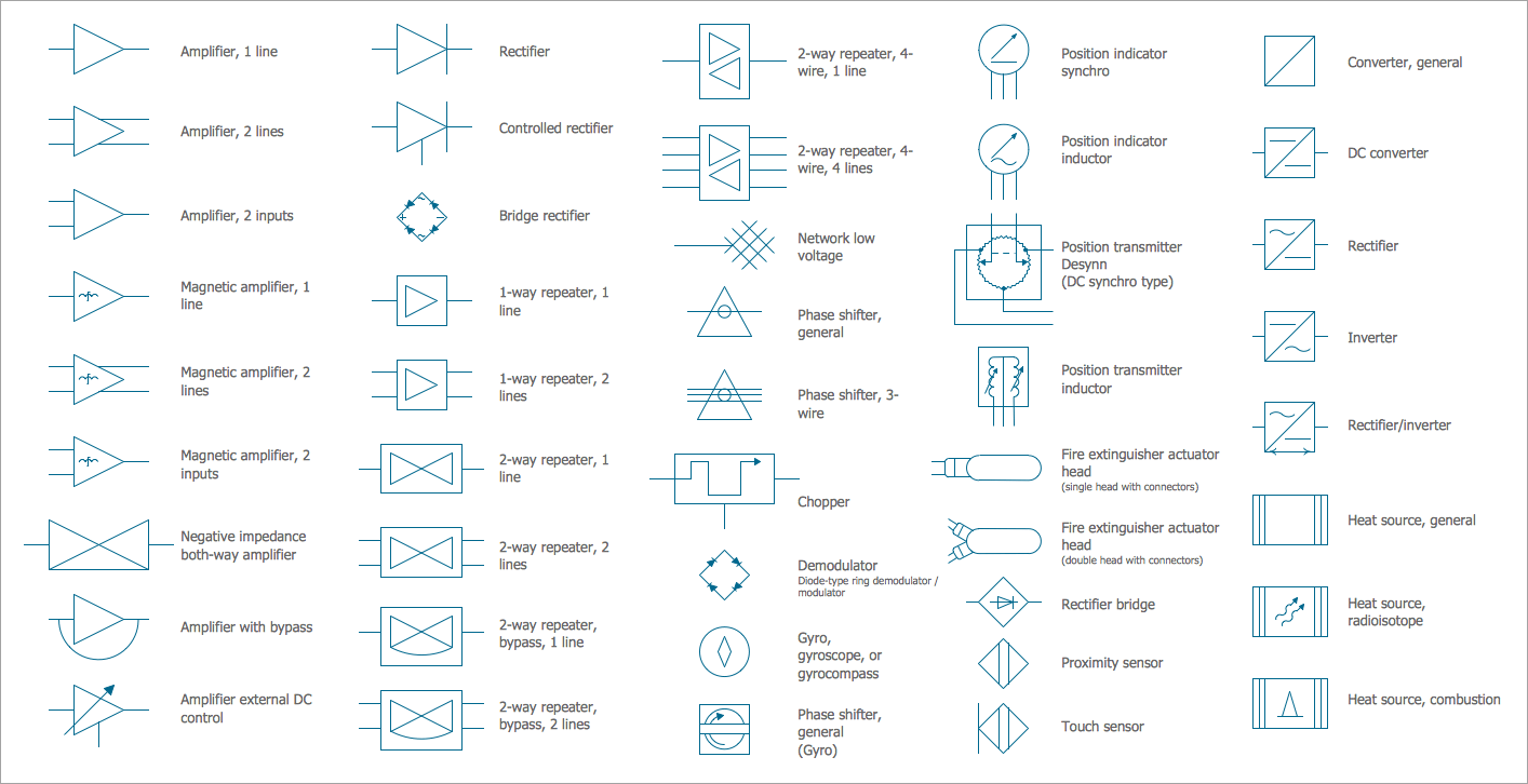
Each symbol represents a specific electrical component or function, allowing professionals to quickly identify and locate key elements within a system. 2 or 3) of the previously published iec 60617 have been incorporated into this database that currently includes some 1900 symbols. These symbols help electrical engineers, technicians, and hobbyists understand the layout and functioning of a circuit without having.
[DIAGRAM] Electrical Wiring Diagram Symbols Pdf
![[DIAGRAM] Electrical Wiring Diagram Symbols Pdf](https://i2.wp.com/paintingvalley.com/drawings/electrical-drawing-symbols-12.png)
By learning these symbols, beginners can quickly identify and interpret the different. By using these symbols consistently, complex electrical information can be communicated in a concise and easily understandable manner. Web our circuit diagram symbol library is schematic and includes many icons commonly used by engineers. Web this physics video tutorial explains how to read a schematic diagram by knowing.
Electrical Schematic Standards Unique Electrical Schematic Standards

Web for example, a simple line with a dot at one end represents a connection point, while a straight line with a triangle at the end represents a resistor. These are the most basic electrical diagram symbols, which can represent simple circuits. Due to the number of variants. Connections and network elements power plant electronic devices logic symbols optic fibre.
Electrical Schematic Drawing Symbols - Web electrical symbols and electronic circuit symbols are used for drawing schematic diagram. The database is the official source of iec 60617. The power supply symbol represents a source of electrical energy, such as a battery or a wall outlet. Web to start developing your schematic reading abilities, it’s important to memorize the most common schematic symbols. Basics 10 480 v pump schematic : A diagram that shows the electrical connections between the parts comprising the controller and that shows electrical connections. From transistors to logic gates, you’ll find icons that are modeled to international standards. Web here is a list of some basic electrical symbols commonly used in schematic diagrams: Due to the number of variants. It is typically depicted as a circle or a rectangle with a plus and minus sign indicating the positive and negative terminals.
Represented by various shapes depending on the type (e.g., npn or pnp) Ieee std 91, ieee standard graphic symbols for logic functions. Web these symbols provide a standardized representation of components such as resistors, capacitors, inductors, diodes, transistors, switches, and more. 2 or 3) of the previously published iec 60617 have been incorporated into this database that currently includes some 1900 symbols. A function block diagram, although it can represent the connection of physical devices, is meant to show a logical connection.
2 or 3) of the previously published iec 60617 have been incorporated into this database that currently includes some 1900 symbols. Represented by two parallel lines. Connections and network elements power plant electronic devices logic symbols optic fibre symbols telecommunication symbols microwave devices flowchart symbols. Commonly used abbreviations in optical, logical and microprocessor circuits component identification abbreviations.
The most fundamental of circuit components and symbols! It is typically depicted as a circle or a rectangle with a plus and minus sign indicating the positive and negative terminals. Web common symbols found in wiring schematics include those for power sources, switches, relays, resistors, capacitors, transformers, motors, and various electrical connections.
Web here is a list of some basic electrical symbols commonly used in schematic diagrams: Our icons are grouped into different symbol families, outlined below. The most fundamental of circuit components and symbols!
Web Some Commonly Used Symbols In An Electrical Schematic Symbols Chart Include:
By learning these symbols, beginners can quickly identify and interpret the different. Web our circuit diagram symbol library is schematic and includes many icons commonly used by engineers. The power supply symbol represents a source of electrical energy, such as a battery or a wall outlet. Basics 13 valve limit switch legend :
A Diagram That Shows The Electrical Connections Between The Parts Comprising The Controller And That Shows Electrical Connections.
Each symbol represents a specific electrical component or function, allowing professionals to quickly identify and locate key elements within a system. Then we'll talk about how those symbols are connected on schematics to create a model of a circuit. The symbols represent electrical and electronic components. From transistors to logic gates, you’ll find icons that are modeled to international standards.
Commonly Used Abbreviations In Optical, Logical And Microprocessor Circuits Component Identification Abbreviations.
Web common symbols found in wiring schematics include those for power sources, switches, relays, resistors, capacitors, transformers, motors, and various electrical connections. Image used courtesy of schneider electric. Web to start developing your schematic reading abilities, it’s important to memorize the most common schematic symbols. Basics 8 aov elementary & block diagram :
Web This Tutorial Should Turn You Into A Fully Literate Schematic Reader!
Web electrical symbols and electronic circuit symbols are used for drawing schematic diagram. Each physical component (i.e resistor , capacitor , transistor ) has a unique schematic symbol. Due to the number of variants. Connections and network elements power plant electronic devices logic symbols optic fibre symbols telecommunication symbols microwave devices flowchart symbols.